All RC systems have the same essential components: a transmitter, a receiver and servos. These parts are sold as assembled, plug-in components; you don’t have to solder anything or know about wiring schematics to install or use them.
Transmitter
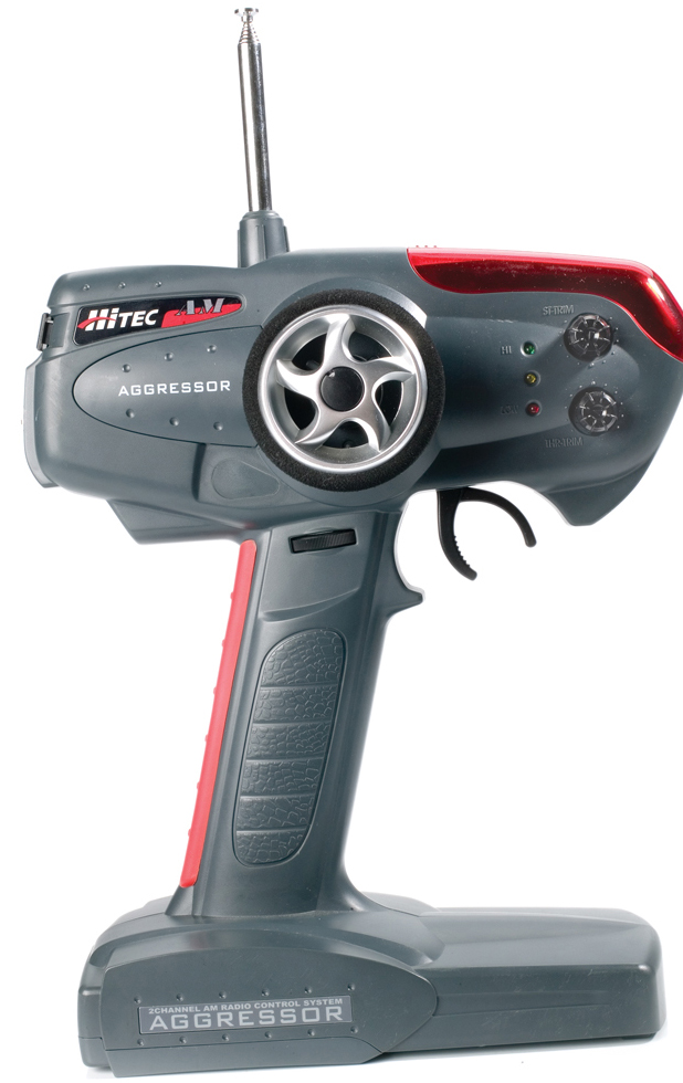
This is the radio of “radio control” and is often simply referred to as the radio. While some drivers prefer airplane-style “stick” radios, the vast majority of drivers use wheel-and-trigger systems. All hobby RC systems are proportional; this means that cars steer, accelerate and brake in proportion to the amount and speed of the input you give the steering or throttle. For example, if you move the steering wheel a little, the car will make a wide, gentle turn. If you turn the wheel sharply, the car will turn sharply.
 Radios also have “channels,” and each channel can operate one function. Most RC car radios have two channels, because a car has two functions to control: steering and throttle. Steering is “channel 1,” and throttle is “channel 2.” Some radios have three channels and are typically used with cars that have reversing transmissions; the extra channel operates the transmission. Tank modelers use radios with 6 or more channels to control light and sound systems, rotating turrets, gun elevation and more—in addition to throttle and steering control.
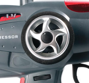
Steering wheel: Turning the wheel to the right steers the car to the right; steering left makes the car turn left. Steering dual rate: This may be a knob or a thumbwheel (as shown). The dual-rate setting controls the total amount of steering throw. This can be used to reduce steering travel to prevent linkages from binding, or to make the car easier to control on slippery surfaces.
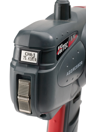
On-off switch & crystal: The switch is a no-brainer. The crystal determines which channel the transmitter is on. Each car gets its own channel to avoid interference.
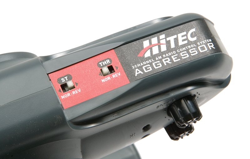
Servo-reversing switches: These will reverse the motion of the servo assigned to each switch so the vehicle operates properly. Suppose that your car turns left when you steer right; if you reverse the steering servo, it will steer properly.
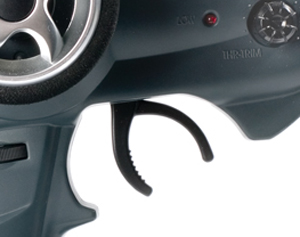
Throttle trigger: Pulling the trigger controls forward throttle while pushing it forward activates the brakes or reverse, depending on the model.

Trim knobs: There is a trim knob for each channel. The knobs are used to adjust the steering or throttle so that the car tracks straight when the steering wheel is centered and does not creep when the trigger is at neutral.
Receiver
As you might have guessed, the receiver receives the signal transmitted by the radio. To avoid interference with other RC systems, the transmitter and receiver must be on the same frequency.
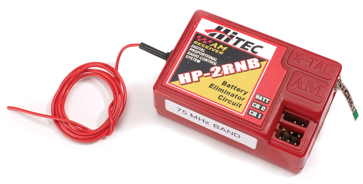
Antenna wire: The most important thing to remember here is: don’t cut the antenna wire! The receiver is tuned for the precise length of wire included, and trimming it will reduce range and reliability.
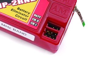
Servo ports: The servos (more on them in a moment) plug into the receiver via these ports. The ports are labeled by channel (1 for steering, 2 for throttle), and the “B” port is for the battery. If you have an engine-powered car, a battery must be carried along to power the receiver and servos. If you have an electric car, the receiver will be powered by the car’s speed control—more on that in a moment, too.
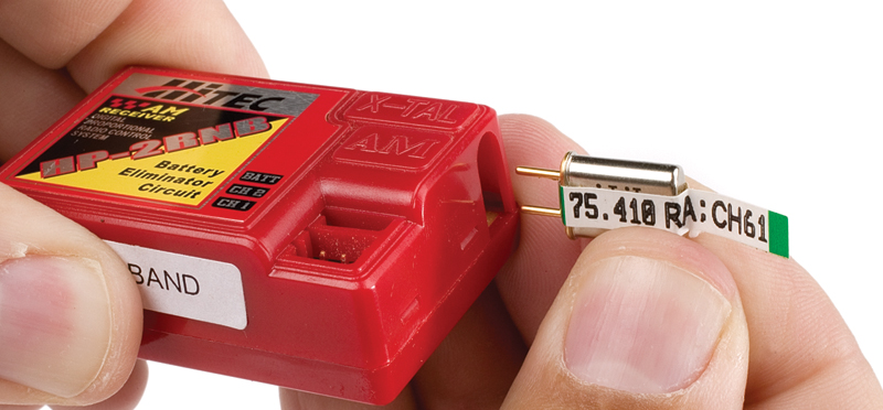
Crystal: The radio system’s frequency is determined by plug-in crystals inserted in the transmitter and receiver. Transmitters and receivers are generally sold in pairs on the same frequency, so you don’t have to worry about it much. But if you’re buying a car to run with a friend’s car, make certain you are on different frequencies. Each frequency is assigned a number, so it’s easy to tell who’s on what.
Servos
These are the “muscles” of your RC car, the parts that actually push and pull the steering linkages and, if you have an engine-powered car, the throttle and brake linkages. Servos are rated by their transit speed (the amount of time it takes the servo to rotate its output shaft 60 degrees) and their torque in ounce-inch (imagine the servo lifting a specified number of ounces using a 1-inch lever).
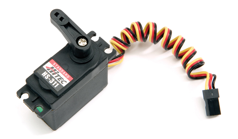
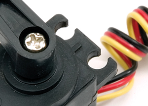
Mounting tabs: These “ears” are used to screw the servo into the car. The spacing is standard so any brand of servo can be used in any car.
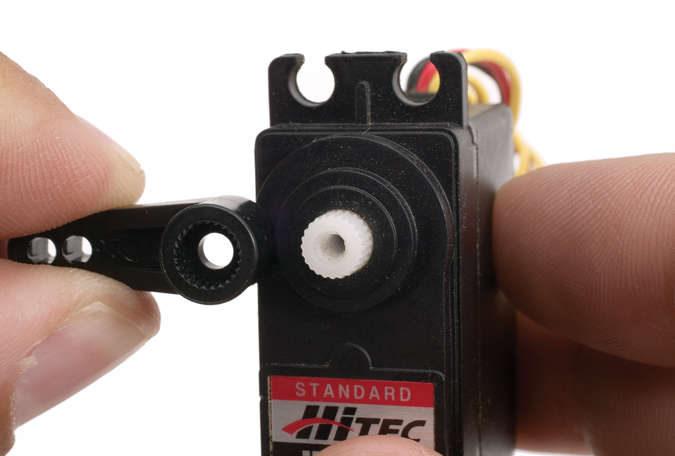
Servo arm: Servos typically come with a few arms of different lengths, and car kits often include a specific arm for the job the servo is doing. All RC kits include arms to fit 25- and 23-spline servos, and many also include 24-spline arms. The output shaft is the part of the servo that actually turns. The ridges on the shaft (above) are called splines. The number of splines varies according to manufacturer (Futaba and Traxxas have 25, Hitec has 24, and all other brands have 23) so a servo arm with the correct number of splines must be used.
Speed control
In an engine-powered car, a throttle servo operates the engine’s carburetor and a mechanical brake. In an electric car, a speed control or electronic throttle is used to vary the motor’s rpm and with it, the car’s speed. The speed control also applies the brake, which is electronic; the motor’s electromagnetic field supplies the stopping power. The speed control simply plugs into the receiver in place of
a throttle servo.

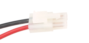
Battery plug: Your car’s battery will plug in here. The standard connector is a “JST” or “Tamiya-style” connector.
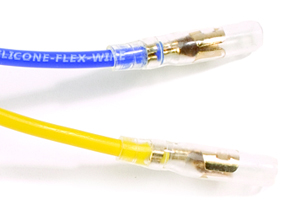
Motor leads: Most speed controls use bullet connectors to connect the speed control to the motor. Racing controllers usually have bare wires that must be soldered to the motor.
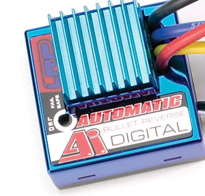
Heat sink: A speed control varies rpm by pulsing the motor on and off many times per second, and this causes heat. Some speed controls are so efficient that they don’t require a heat sink, but many have aluminum fins to help dissipate heat. Located near the heat sink is theSetup button or LED. With few exceptions, a programming button is used to match the speed control to the transmitter so the speed control can “learn” what signals correspond with neutral, full throttle, and brake. The exact procedure varies with each manufacturer, but generally, all you have to do is hold the button down until a light comes on and then apply full throttle and full brake until the speed control blinks to let you know it is set properly. This LRP AI speed control sets itself automatically.
On/off switch: It isn’t hard to guess what this does. But for maximum safety, you should always disconnect the battery when you’ve finished running your car instead of relying on the switch.
The post How To: The Basics of Radio Control appeared first on RC Car Action.


