OK, back at the bench. After skipping ahead to the transmission for Part 3, I’m paging back through the manual to the driveshafts. You can click the pages and pictures to enlarge…
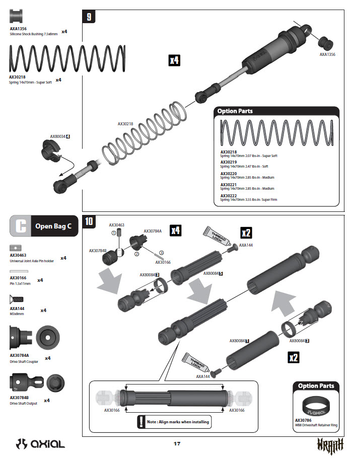
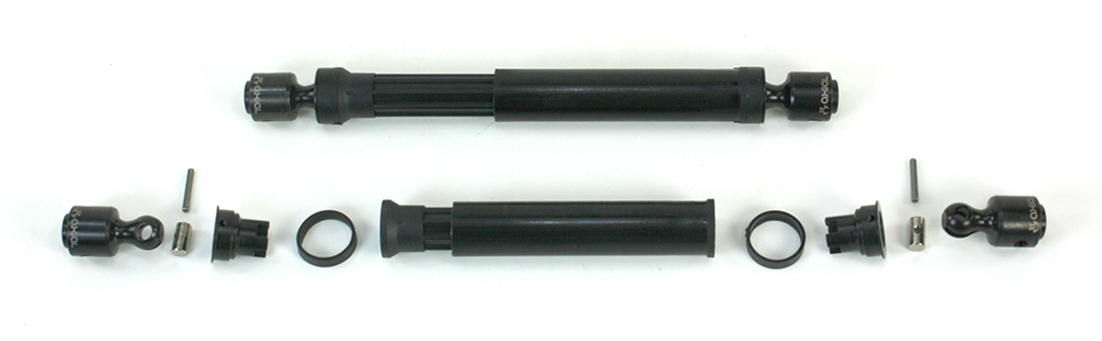
The Wraith’s shafts are telescoping plastic units with curvalinear splines and machined steel CV-style joints. The plastic rings slip over the “bell” of the CV joint to prevent the cross-pins from sliding out. If you enlarge the manual page, you’ll see how the CV joints are secured by a screw inserted within each half-shaft.
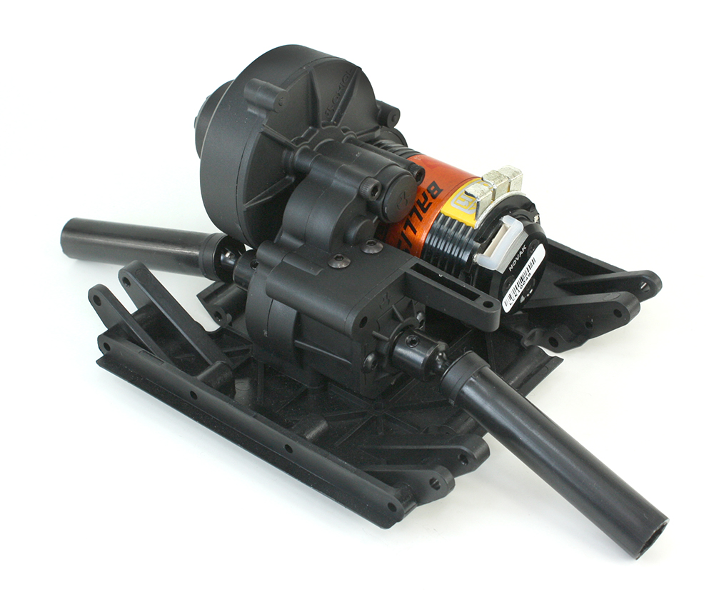
The shafts are installed on the transmission (which was assembled in Part 3) and the tranny is installed on the chassis’ skid plate. Note that I’ve installed the motor with the solder tabs pointing straight up. I later discovered this interferes with the interior, so I rotated the motor to angle the tabs toward the transmission.
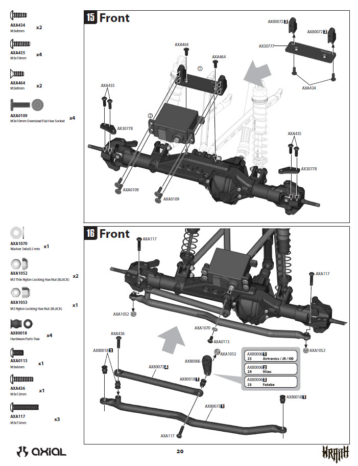
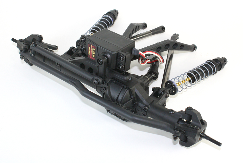
Back to the front axle for shock, linkage, and servo installation. No surprises here, but do set the servo mount spacing correctly before installing the mounting plate on the axle–once the plate is installed, you can’t access the servo mounts’ screws to adjust their spacing.
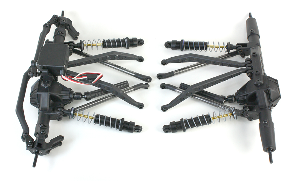
Axles with linkages, shocks, and driveshafts installed. Note that the axle pumpkins are both on the left side of the truck.
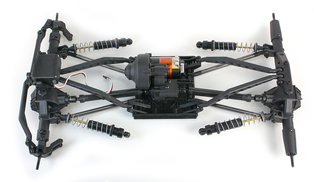
With the exception of the shocks, everything bolts to the skidplate.
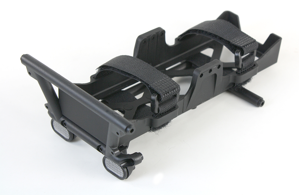
Moving on…here’s the battery tray, which also holds the taillights. There are also four lights in the front bumper. The Wraith is “LED ready,” and Axial offers a pre-wired light kit that’s easy to install.
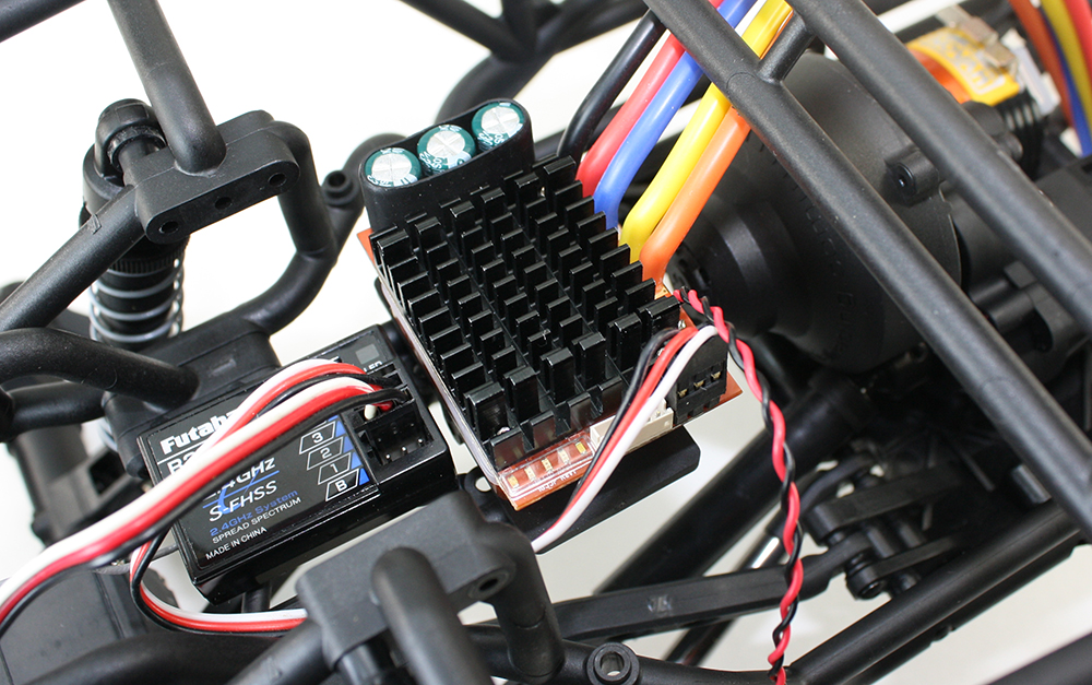
I didn’t bother detailing the tube-frame assembly process–the photos look like I’m wrestling with coat hangers. I noticed that the Novak Crusher speed control, when mounted vertically per the instructions, rubbed the gear cover. I installed it flat instead, and skipped the Wraith’s sealed receiver box as I don’t plan on dunking the truck. The receiver is from my Futaba 4PL, which has since been replaced by the telemetry-equipped 4PLS.
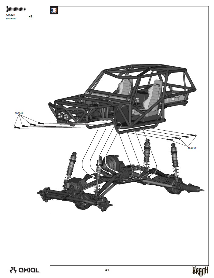
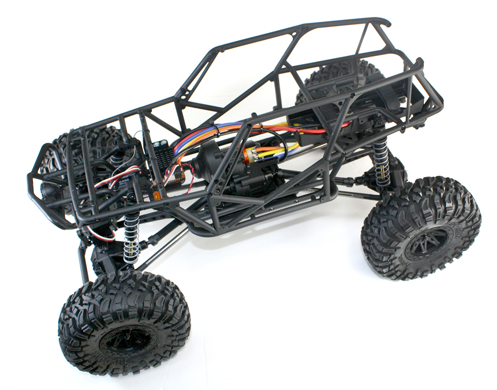
I’m skipping ahead again. The manual calls for tube-frame to be assembled in halves so the interior can be sandwiched between them, but there’s enough flexibility to slip the interior into the chassis after it’s assembled–all you need to do is remove the roof section and the bars that run behind the dash. As you can see in the manual page, the tube frame simply bolts to the skid plate. The only other connecting points are the shocks. In the future, I’ll install a connector between the speed control and motor so I can lift off the tube-frame without de-soldering the motor wires.
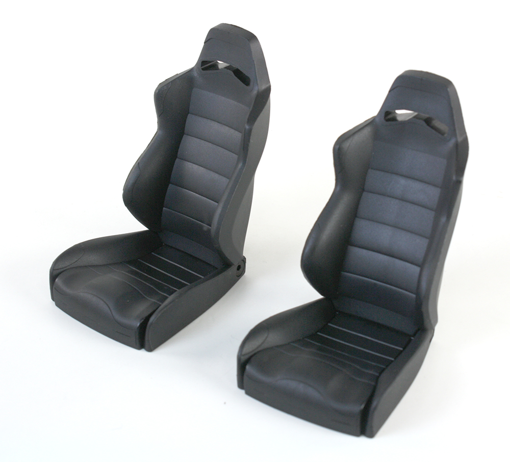
Interior construction begins with the seats, which are nicely sculpted (and officially licensed) replicas of Corbeau LG1 buckets. They’re solid plastic, and each seat weighs two ounces. That doesn’t sound like much, but when you hold the seat in your hand, it’s hefty. More weight, more traction, right?
…and I’m out of time for today. We’re in the home stretch, we’ll wrap it up in Part 5!

The post Axial Wraith Build, Part 4 appeared first on RC Car Action.


